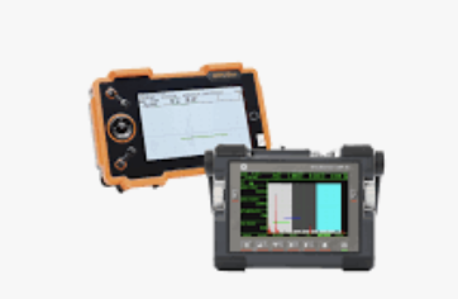
A blip on a screen and a rejected weld are not the same thing, even though it’s tempting to treat them that way under schedule pressure. Between the moment an instrument registers a response and the moment someone decides what to do about it sits a chain of judgment calls that the raw signal alone can never make on its own. This article traces that chain, from what an instrument actually produces through to the engineering decision that follows, and why skipping a link in it undermines the whole inspection.
An NDT Instrument Produces Evidence, Not a Final Inspection Decision
An instrument reports a response to physical conditions rather than a verdict. Getting from one to the other takes several distinct steps, and three of them matter enough to spell out before going further.
An Indication Is Not Automatically a Confirmed Discontinuity or Defect
An indication is simply a response the instrument registers. Whether it represents a genuine discontinuity in the material, or whether that discontinuity rises to the level of a defect under the applicable acceptance criteria, remains entirely open until someone works through the next steps. Collapsing these terms into interchangeable shorthand, as often happens on a busy shop floor, blurs exactly the distinction a careful inspection depends on.
Interpretation Determines Whether an Indication Is Relevant to the Inspection
NDT interpretation — the term stands for nondestructive testing — is the step that sorts a genuine signal from noise, geometry, or a harmless surface feature. An indication only becomes relevant once interpretation confirms it actually reflects something in the material worth further attention.
This step happens before any comparison against acceptance limits. Skipping straight to that comparison risks evaluating something that was never a real indication to begin with.
Different NDT Methods Reveal Different Types of Evidence About the Component
Each NDT method reports a different physical phenomenon standing in for the underlying material condition:
- Ultrasonic testing reports reflected sound energy.
- Radiographic testing captures density variations on film or a digital detector.
- Magnetic particle and liquid penetrant methods report visible accumulations at the surface.
Nondestructive testing as a field exists precisely because no single phenomenon tells the whole story on its own.
Verify the Test Foundation Before Interpreting the Result
A result built on a shaky foundation rarely improves no matter how carefully it gets read afterward. Checking that foundation comes first, and it breaks down into four separate confirmations worth running through in order.
Confirm the Inspection Objective, Procedure, and Required Technique
Start by confirming what the inspection is actually meant to answer. A written NDT inspection procedure then governs exactly how that answer gets obtained, specifying the technique, parameters, and acceptance path to follow.
A technique chosen without reference to this procedure produces results that may be technically accurate and still useless for the question at hand. The same risk applies when the right technique gets applied against the wrong objective entirely.
Check Calibration or Reference Verification Appropriate to the NDT Method
Every method carries its own calibration or reference-check routine, and skipping it undermines everything measured afterward. NDT calibration against known NDT reference standards establishes that the instrument responds predictably to a known condition before it gets trusted to characterize an unknown one.
Make Sure the Instrument, Probe, Sensor, or Accessory Matches the Intended Technique
Reliable professional NDT equipment, properly matched to the specific technique and material at hand, is what turns a correct procedure into a correct result. A probe frequency mismatched to the material, or a sensor sized wrong for the geometry, can quietly shift results away from what the procedure actually assumes.
Account for Material, Geometry, Surface Condition, and Test Environment
A handful of factors shape how a given method behaves on a specific component, without ever showing up directly in the displayed result:
- Conductivity, density, or grain structure within the material itself.
- The physical form of the part, including curves, edges, and thickness transitions.
- How well the surface was prepared or cleaned before testing began.
- Ambient temperature, humidity, and lighting conditions at the time of the scan.
Distinguish Relevant Indications From Test Artifacts and Non-Relevant Responses
A signal on the display doesn’t automatically earn the same suspicion as every other. Sorting the real from the irrelevant is a skill of its own, built around a handful of recurring traps.
Part Geometry and Known Features Can Produce Responses That Resemble Flaws
A sharp edge or an abrupt thickness change can trigger a response that looks, at first glance, exactly like a genuine discontinuity. Fillets, counterbores, and other intentional design features behave the same way, producing a signal rooted in shape rather than damage.
Mistaking one of these for a flaw wastes time and, worse, can erode confidence in results that were actually sound. A quick check against the part’s drawing or known design features usually resolves the question fast. That comparison, run before any response gets treated as significant, filters out a meaningful share of false alarms before they ever reach evaluation.
Coupling, Lift-Off, Surface Condition, Alignment, and Other Technique Variables Can Affect the Signal
Several technique-specific variables can distort a signal without any actual change in the material underneath. Common culprits include:
- Inconsistent coupling between an ultrasonic probe and the test surface.
- Lift-off variation in eddy current scanning.
- Surface roughness interfering with magnetic particle accumulation.
- Probe or beam misalignment relative to the suspected flaw orientation.
Ruling these out before accepting a signal as genuine saves considerable time chasing phantom problems.
Check Repeatability, Location, and Supporting Evidence Before Classifying an Indication
Reliable NDT indications tend to reproduce consistently under repeated scanning, and confirming that before classification strengthens confidence considerably. A few checks worth running before treating a signal as settled:
- Does the indication reappear on a repeat scan of the same area?
- Does its location align with a known stress concentration, weld zone, or similar feature?
- Does supporting evidence from a different angle or technique corroborate it?
Interpret Results Within the Limits of the NDT Method
Every method has a ceiling on what it can honestly claim to confirm. Running past that ceiling is one of the quieter ways an inspection goes wrong, and it tends to happen in a few specific, avoidable ways.
Detection Capability Does Not Mean Every Discontinuity Will Be Found or Characterized
NDT limitations mean that a clean scan confirms nothing was detected within the method’s sensitivity, orientation coverage, and depth capability. It does not confirm the component is free of every possible discontinuity. A crack oriented unfavorably to an ultrasonic beam, for instance, can sit undetected through an otherwise thorough examination.
Signal Amplitude, Image Appearance, or Instrument Response Does Not Automatically Establish Structural Significance
A large signal is not automatically a serious flaw, and a small one is not automatically harmless. Signal amplitude tracks a handful of physical properties, none of which map directly onto structural severity without further evaluation:
- Reflectivity of the discontinuity relative to the surrounding material.
- Density difference captured on a radiographic image.
- Surface accumulation of particles or dye at the indication site.
Use a Complementary NDT Method Where Appropriate When the First Examination Cannot Answer the Remaining Question
Where one method leaves genuine ambiguity, a second technique built around a different physical principle often closes the gap. A surface method confirming a crack’s presence, paired with ultrasonic testing to establish its depth, is a common example of two methods covering each other’s blind spots.
Turn the Inspection Findings Into a Defensible Decision
Getting a clean, well-interpreted result is still only part of the job. Converting that result into something an organization can actually act on takes three more deliberate steps.
Evaluate Relevant Indications Against the Correct Acceptance Criteria
Evaluation is the step where a confirmed, relevant indication gets measured against the applicable NDT acceptance criteria. This comparison is what finally determines whether a discontinuity counts as acceptable under the governing code, or crosses into defect territory requiring further action.
Ensure Interpretation, Evaluation, and Reporting Are Performed by Appropriately Qualified Personnel Where Required
NDT personnel qualification standards exist because interpretation and evaluation both require trained judgment. A technician certified to perform a scan is not automatically qualified to evaluate its results against engineering criteria, and most codes draw that distinction explicitly.
Separate the NDT Finding From the Final Engineering, Repair, or Fitness-for-Service Decision
An evaluated finding still isn’t the same thing as a repair order or a fitness-for-service determination. That final call often belongs to an engineer weighing the finding against loading conditions, service history, and the consequences of failure, factors that sit outside what any NDT inspection results report alone can capture.
What Actually Separates a Trustworthy Finding From a Lucky Guess
A clean scan and a correctly interpreted scan can look identical on paper, yet only one deserves trust. The difference lies in whether each judgment call along the chain was made deliberately. An inspection program earns credibility through honesty about which flaws it was built to catch, rather than a claim to catch them all. That honesty is what separates genuine flaw detection from a result that merely happened to be right.